Brand: TOSHIBA
Category: Telephone
Document Type: Manual
Language: EN
Brand: TOSHIBA
Category: Telephone
Document Type: Manual
Language: EN
Uploaded: Nov. 21, 2025, 8:25 p.m.
Manual Publish Date: 2000-06-01
No warranty information found in the provided pages.
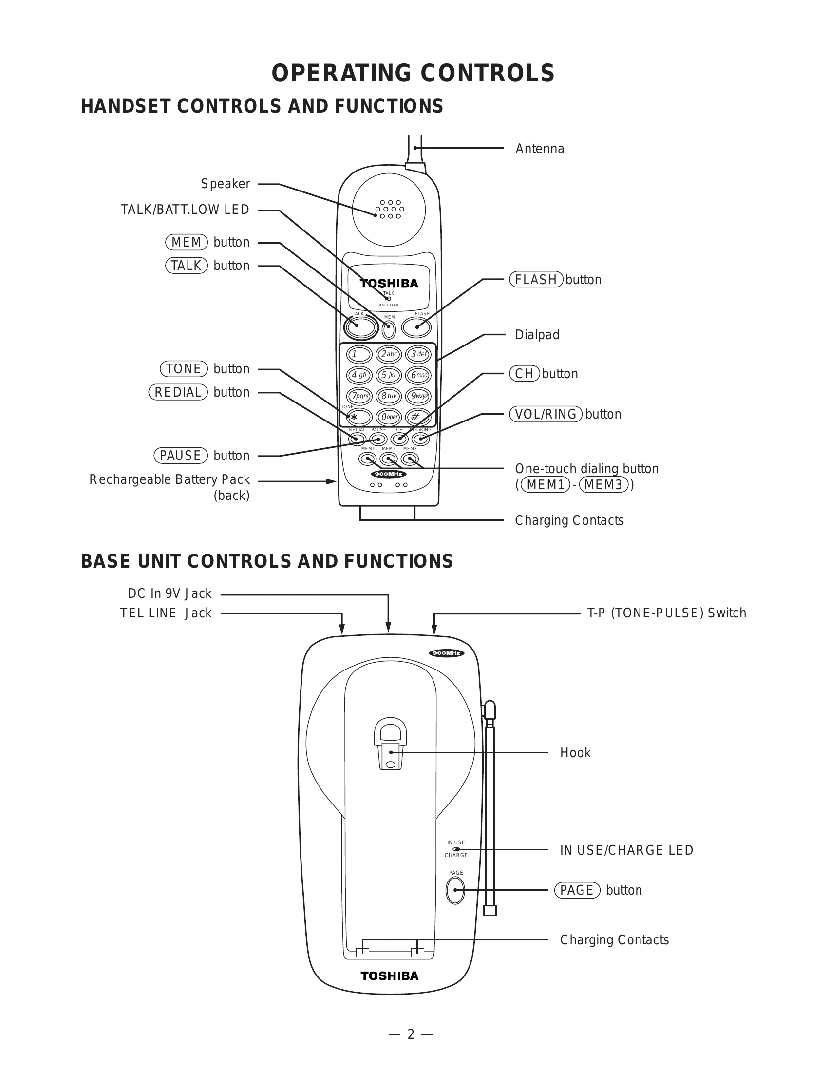
Handset Controls: Features include a Speaker, TALK/BATT.LOW LED, MEM button for memory functions, TALK button for initiating calls, TONE button for tone dialing, REDIAL button for redialing, PAUSE button for pauses in dialing, Antenna, FLASH button, Dialpad for number entry, CH button, VOL/RING button for volume and ringtone adjustment, and One-touch dialing buttons (MEM1-MEM3).
Base Unit Controls: Includes DC In 9V Jack, TEL LINE Jack, T-P (TONE-PULSE) Switch, Hook for handset placement, IN USE/CHARGE LED to indicate status, and PAGE button to locate the handset.
Alignment Procedure: Involves connecting test equipment like Power Meters, Frequency Counters, Deviation Meters, and AF Generators to specific test points on both the Base Unit and Handset PCBs. Adjustments are made using components like RT301, CT1, RT3, L3, RT2, RT1, RT501, CT401, RT403, L402, RT402, and RT401 to ensure correct TX Power, TX Frequency, TX Modulation, Discriminator Voltage, RX AF Voltage, and SQ Point.
| Trouble Condition | Symptom | Check Item | Action / Solution |
|---|---|---|---|
| 1. The bell does not ring. | When PAGE SW of base is pressed, does ringer on handset ring? | PAGE SW | NG: See 2. (Bell & page do not ring) OK |
| When TEL SG is joined with base to make bell signal, is there pulse wave at pin 4 of IC4? | IC4, TEL network circuit | NG: Check IC4 and TEL network circuit. OK | |
| Is there pulse wave at pin 21 of IC5? | IC5, peripheral circuit | NG: Check R58, C45 and R59. OK: Check IC5 and its peripheral circuit. | |
| (Base Unit Reset) | Set T/P switch to TONE. Disconnect AC adaptor & line. Press PAGE, plug AC adaptor. Keep pressing PAGE for 3 sec. Press PAGE again, IN USE LED lights, base unit resets. | ||
| (Handset Caller ID Deletion) | Disconnect battery. Connect battery pressing * and #. Press buttons for 3 sec. Keep pressing, beep tone & TALK LED light. Press MEM key, handset resets. | ||
| 2. The bell does not ring & page does not ring. | Can base and handset be connected? | Connection | NG: See 3. (Cannot be connected). OK |
| Press handset DIAL key in TALK MODE. Can key touch sound be heard from ringer? | Handset keys, IC5 | NG: Check IC404. OK: At Q408 collector, can pulse wave be seen? NG: Check R454, R457 and D402. OK: Check RINGER Y401. | |
| When PAGE SW of base is pressed, does pin20 of IC5 change from high to low? | IC5 peripheral circuit | NG: Check R55, R77 and S1. OK: Check IC5 and its peripheral circuit. | |
| 3. The base and handset cannot be connected. | Check if base can set in test mode 1. | IC5 peripheral circuit | NG: Check IC5 and its peripheral circuit. OK: Check TX POWER & FREQUENCY on base unit. |
| Press PAGE key 2 times, check deviation of TX data (~8 kHz Dev.). | Base RF unit | NG: Check Base RF unit. OK: Check 250 Hz data waveform at 'MOD' of RF unit. NG: Check RT3, R40, R68, R69, R53, R70 and C79. OK: Check Base RF unit. |