Brand: TOSHIBA
Category: Air Conditioner
Document Type: Manual
Language: EN
Brand: TOSHIBA
Category: Air Conditioner
Document Type: Manual
Language: EN
Uploaded: Nov. 21, 2025, 6:33 p.m.
Manual Publish Date: 2005-06-01
This manual provides service information and does not contain specific warranty period details.
This manual covers the service and installation procedures for TOSHIBA Split Wall Type Air Conditioners, models RAS-13NKV-E/RAS-13NAV-E and RAS-16NKV-E/RAS-16NAV-E. It details specifications, refrigerant handling (R410A), construction views, wiring diagrams, electrical part specifications, refrigerant cycle and control block diagrams, operation descriptions, installation procedures, troubleshooting, parts replacement, and exploded views.
Key sections include:
The manual emphasizes the importance of using correct tools and procedures, especially when working with R410A refrigerant due to its higher operating pressure.
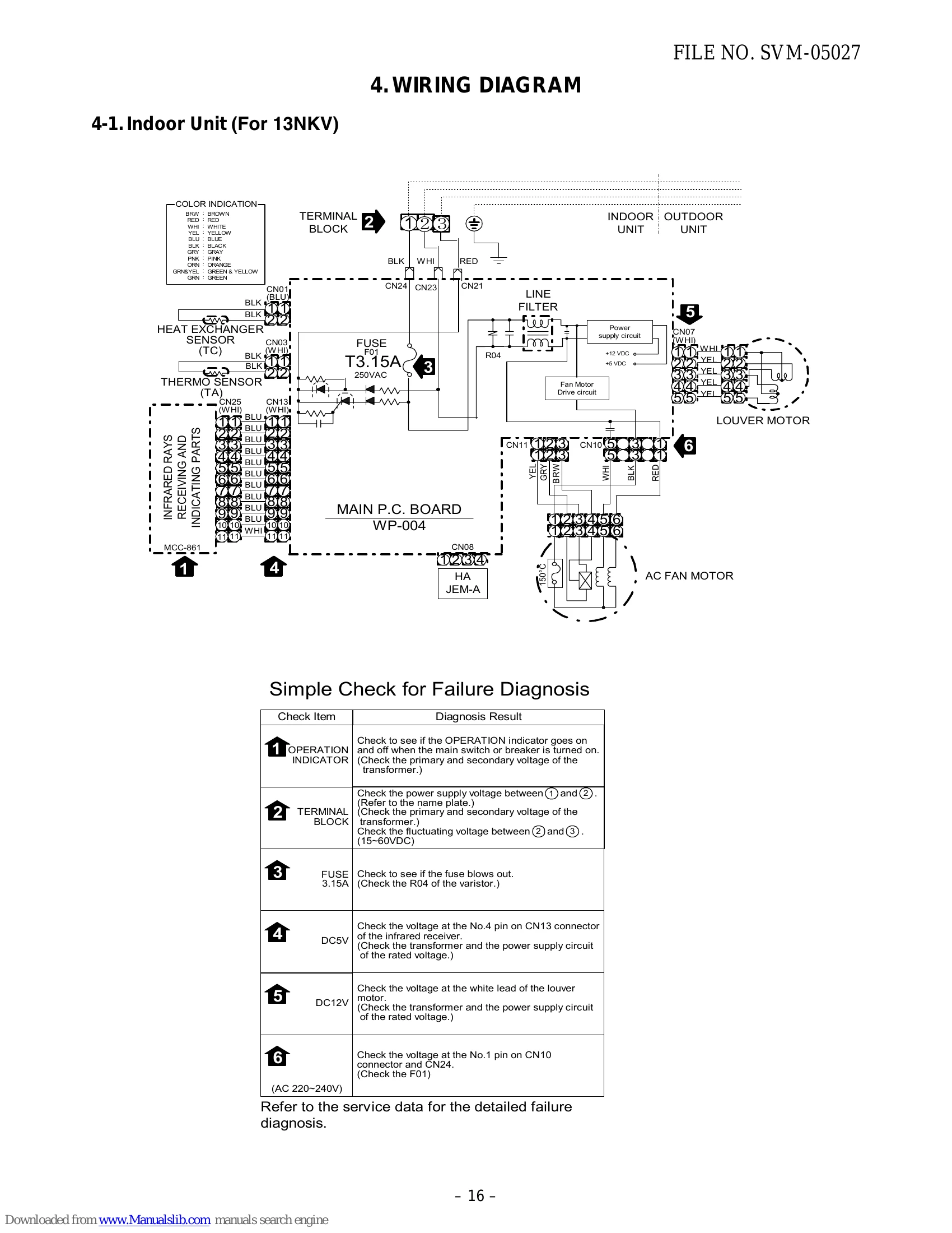
| Check Item | Diagnosis Result |
|---|---|
| 1 OPERATION INDICATOR | Check to see if the OPERATION indicator goes on and off when the main switch or breaker is turned on. (Check the primary and secondary voltage of the transformer.) |
| 2 TERMINAL BLOCK | Check the power supply voltage between ① and ② (Refer to the name plate.) (Check the primary and secondary voltage of the transformer.) |
| Check the fluctuating voltage between ② and ③ (15~60VDC) | |
| 3 FUSE (F01) 3.15A | Check to see if the fuse blows out. (Check the R04 of the varistor.) |
| 4 DC5V | Check the voltage at the No.4 pin on CN13 connector of the infrared receiver. (Check the transformer and the power supply circuit of the rated voltage.) |
| 5 DC12V | Check the voltage at the white lead of the louver motor. (Check the transformer and the power supply circuit of the rated voltage.) |
| 6 | Check the voltage at the No.1 pin on CN10 connector and CN24. (Check the F01) |