1. SAFETY INSTRUCTIONS
- Ensure compliance with Health & Safety, local authority, and general workshop practice regulations.
- Be cautious of fingers when closing the sliding top to avoid pinching.
- Load trolley evenly, keeping the center of gravity near the trolley's center.
- Maintain a clean, uncluttered, and well-lit work area.
- Keep the trolley clean and tidy.
- Use wheel locks to prevent inadvertent movement.
- Keep children and unauthorized persons away.
- Do NOT overload (Max Capacity 100kg).
- Use only for its intended purpose.
- Do NOT stand on the trolley, use it as a ladder, or allow others to ride.
- Do NOT leave unattended if loaded, unless secured.
- Do NOT use on uneven ground or over curbs/steps; use a ramp.
- Do NOT use if damaged, especially wheels.
- Note: Side drawers open only when the sliding top is open.
- Note: Assembly requires assistance.
2. INTRODUCTION & SPECIFICATION
- Heavy gauge steel construction with lockable sliding top.
- Smooth ball bearing runners for the top and twin drawers.
- Drawers locked when top is closed.
- Two fixed wheels and two locking castors.
- Suitable for tools and parts.
- Some self-assembly required.
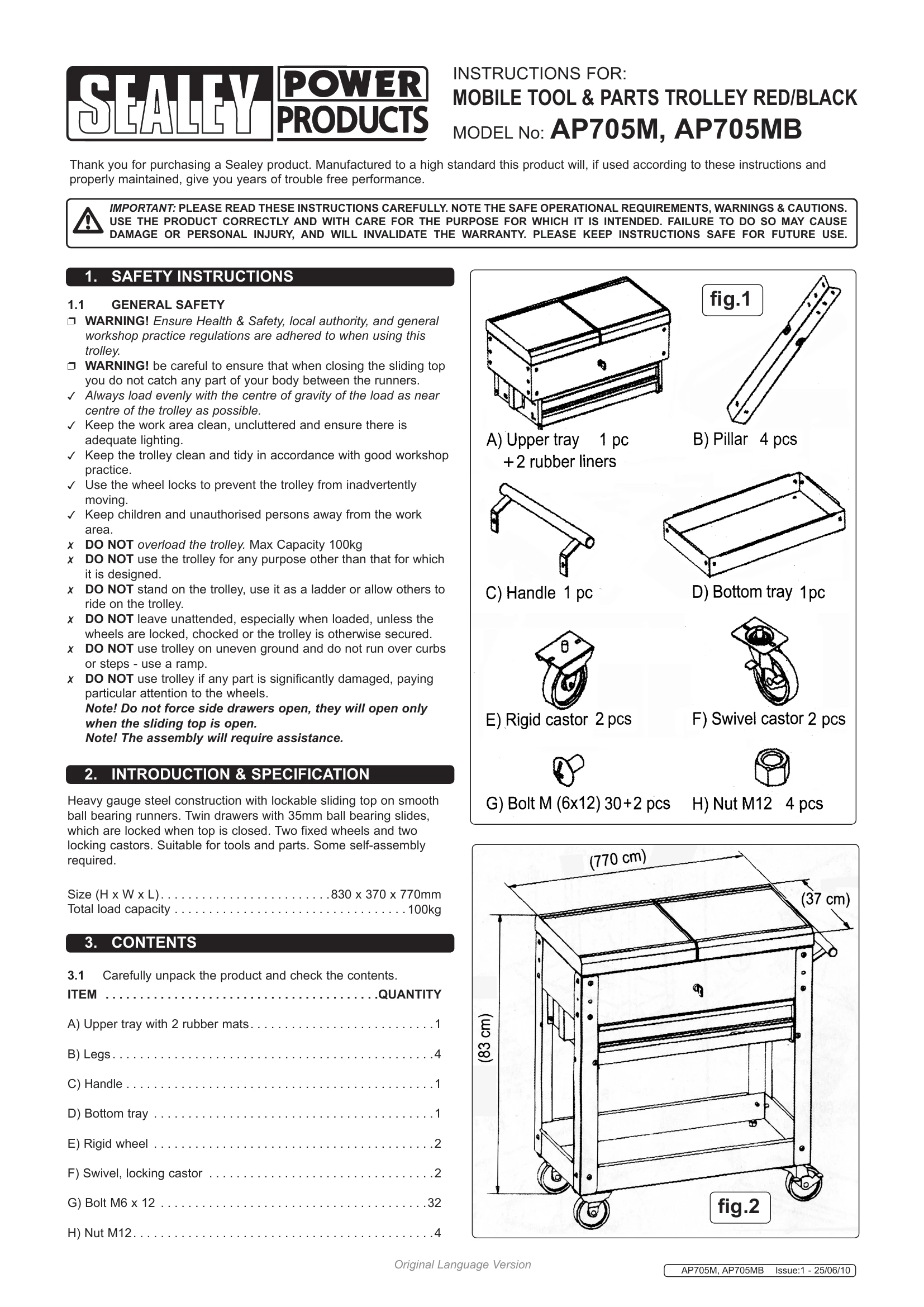
- Dimensions: 830 x 370 x 770mm
- Total load capacity: 100kg
3. CONTENTS
- Check all items against the contents list after unpacking.
4. ASSEMBLY
- Remove trolley from the box and unlock.
- Close and lock the trolley before assembly.
- Attach fixed wheels (E) to one end of the bottom tray (D) using M12 nuts (H).
- Attach castors (F) to the other end using M12 nuts (H).
- Attach the four upright pillars (B) to the bottom tray (D) using bolts (G). Ensure correct orientation.
- With assistance, position the upper tray unit and fix with bolts.
- Further secure the unit with additional bolts.
- Fix the handle (C) using bolts (G).
- Insert additional bolts as shown in fig.6.