Brand: SAMSUNG
Category: Air Conditioner
Document Type: Manual
Language: EN
Brand: SAMSUNG
Category: Air Conditioner
Document Type: Manual
Language: EN
Uploaded: Nov. 21, 2025, 6:06 p.m.
Manual Publish Date: 2017-01-01
This manual does not contain specific warranty period information.
| No. | Parts | Procedure | Remark |
|---|---|---|---|
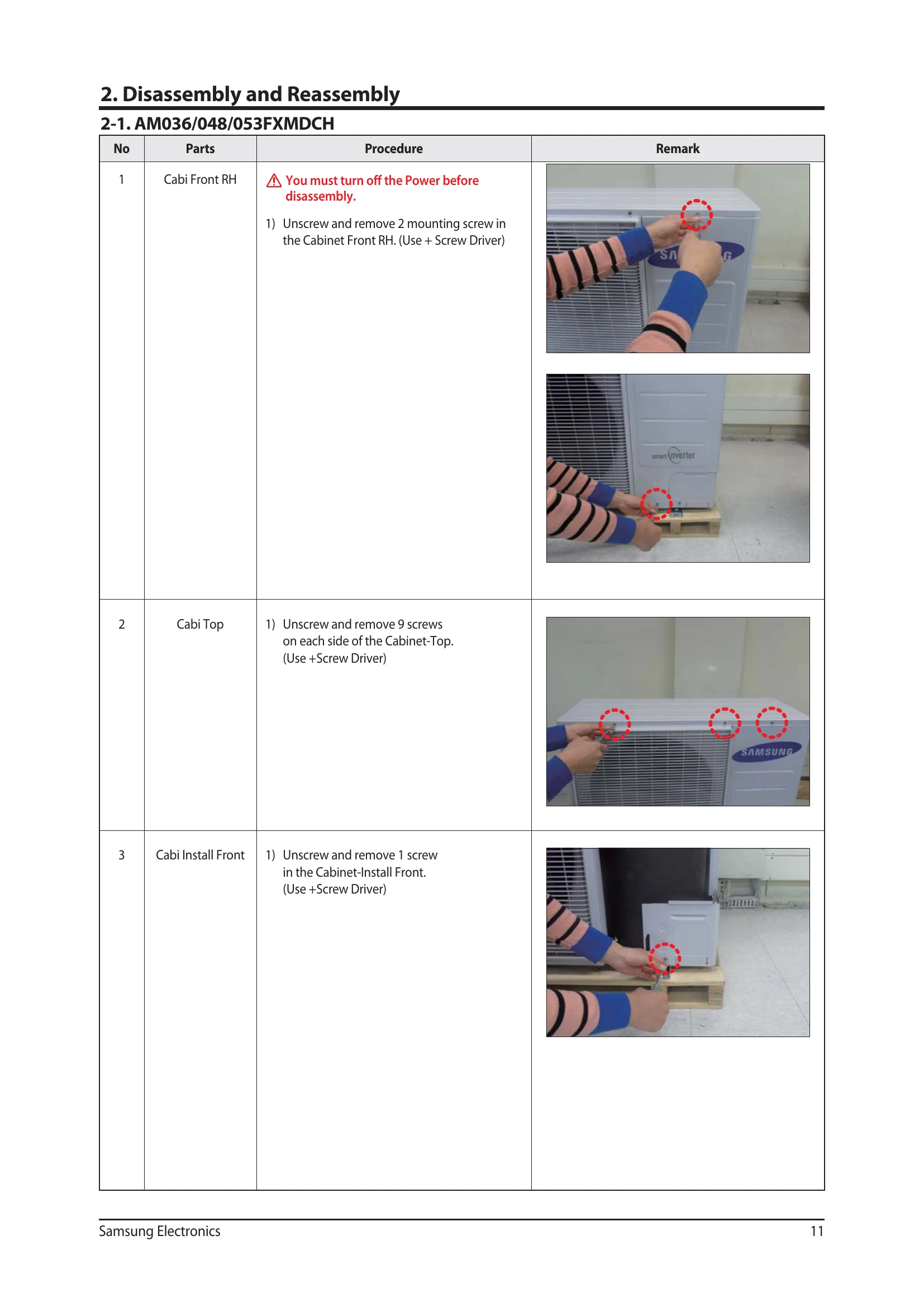
| 1 | Cabi Front RH | 1) Unscrew and remove 2 mounting screw in the Cabinet Front RH. (Use + Screw Driver) | |
| 2 | Cabi Top | 1) Unscrew and remove 9 screws on each side of the Cabinet-Top. (Use +Screw Driver) | |
| 3 | Cabi Install Front | 1) Unscrew and remove 1 screw in the Cabinet-Install Front. (Use +Screw Driver) | |
| 4 | Guard Cond | 1) Pull the sensor from Guard Cond. 2) Unscrew and remove 4 screws in the Guard Cond. (Use + Screw Driver) |
|
| 5 | Cabi Back RH | 1) Pull the sensor from Cabi Back RH. 2) Unscrew and remove 4 screws on each side of the Cabinet Back RH. (Use + Screw Driver) |
|
| 6 | Cabi Install Back | 1) Unscrew and remove 1 screw in the Cabinet-Install Back. (Use +Screw Driver) | |
| 7 | Cabi Front LF | 1) Unscrew and remove 10 screws in the Cabinet-Front LF. (Use +Screw Driver) | |
| 8 | Fan | 1) Turn 2 mounting nuts as shown in the picture and remove it. (Use L Wrench or Monkey Spanner or Socket Wrench) | |
| 9 | Motor | 1) Separate the Fan Propeller. 2) Unscrew and remove the 8 Motor mounting screws. (Use +Screw Driver) 3) Disconnect the Motor wire from Ass'y Control Out. |
|
| 10 | Bracket Motor | 1) Unscrew and remove 2 mounting screws in Bracket Motor. (Use + Screw Driver) | |
| 11 | Control Out | 1) Disconnect 9 Connectors from Ass'y control Out. 2) Unscrew and remove 1 mounting screw in Control Out. (Use + Screw Driver.) 3) Separate Ass'y Control Out. |
|
| 12 | Ass'y Tube EEV | 1) Purge the Coolant first. 2) Separate 2 parts of the pipe using a welder. When removing the compressor, Heat Exchanger and Pipe, purge the refrigerant inside the Compressor completely and remove the pipe with a welding flame. |
|
| 13 | Ass'y Tube Suction | 1) Separate 2 parts of the pipe using a welder. | |
| 14 | Ass'y Tube 4Way | 1) Unscrew and remove 2 mounting screws in Oil Separator. (Use + Screw Driver.) 2) Separate 2 parts of the pipe using a welder. |
|
| 13 | Compressor | 1) Unscrew and remove 1 mounting nut in bottom of the cover. (Use Adjustable Wrench) 2) Separate the Compressor Felt. 3) As shown in the picture, unscrew and remove 3 mounting screws from the bottom. (Use L-Wrench or Monkey Spanner or Socket Wrench) |
|
| 16 | Cond Out | 1) Unscrew and remove 3 screws on each side of the Ass'y Cond Out. (Use + Screw Driver) |