Brand: Motorola
Category: Networking
Document Type: Manual
Language: EN
Brand: Motorola
Category: Networking
Document Type: Manual
Language: EN
Uploaded: Nov. 21, 2025, 8:11 p.m.
Manual Publish Date: 2012-07-13
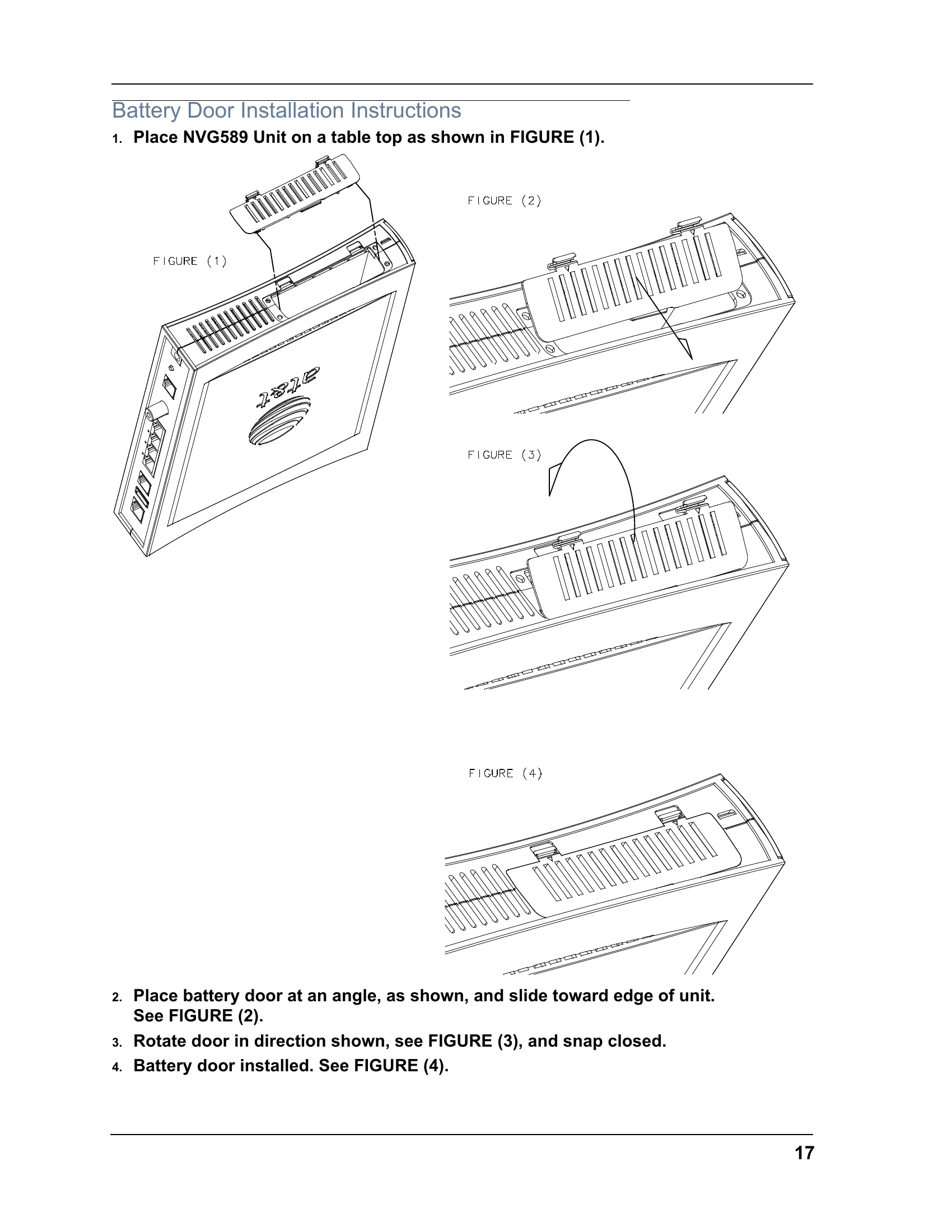
None
| LED | Action |
|---|---|
| Power* | = The device is powered. = A Power-On Self-Test (POST) is in progress = A POST failure (not bootable) or device malfunction occurred. = during firmware upgrade (see below) Off = The unit has no AC power. |
| *During Firmware Upgrade | During the software installation, you will lose internet and phone service. The LEDs will function as follows: 1. As firmware is being loaded into flash, the LEDs will operate normally as described. 2. The installation will take a few minutes During this phase, the Power LED will flash (flash writing to memory) and all other LEDs will be off. 3. The Gateway will restart automatically. As the device reboots, the POWER ON LED behavior will happen. |
| During Boot process | • Power LED = • All other LED = OFF If the device does not boot, and fails its self test or fails to perform initial load of the bootloader: • Power LED = • ALL other LED = OFF If the device boots and then detects a failure: Power LED = starting POST and then all LEDs will , including Power LED. |
| Battery | = Battery in place but not being used. = Battery charging. = Battery backup mechanism has a fault. = Battery needs to be replaced. = Battery in use. = Low battery. Off = No battery or battery has no charge. Cycle between all colors = Battery conducting self-test. |
| Ethernet | = Powered device connected to the associated port (includes devices with wake-on-LAN capability where a slight voltage is supplied to the Ethernet connection). = Activity seen from devices associated with the port. The flickering of the light is synchronized to actual data traffic. Off = The device is not powered, no cable or no powered devices connected to the associ- ated ports. |
| Wireless | = Wi-Fi is powered. = Activity seen from devices connected via Wi-Fi. The flickering of the light is synchronized to actual data traffic. Off = The device is not powered or no powered devices connected to the associated ports. |
| HomePNA | = Powered device connected to the associated port (includes devices with wake-on-LAN capability where a slight voltage is supplied to the Ethernet connection). = Activity seen from devices associated with the port. The flickering of the light is synchronized to actual data traffic. Off = The device is not powered, no cable or no powered devices connected to the associ- ated ports. |
| Broadband 1**, 2 |
= Good broadband connection (i.e., good DSL Sync or Gigabit Ethernet). = Attempting broadband connection (i.e., DSL attempting sync). & = If the broadband connection fails to be established for more than three consecutive minutes the LED switches to when attempting or waiting to establish a broadband connection alternating with a five second steady This pattern continues until the broadband connection is successfully established. = No DSL signal on the line. This is only used when there is no signal, not dur- ing times of temporary 'no tone' during the training sequence. Off = The device is not powered. ** Broadband 1 LED is also the Gigabit ethernet WAN LED when that is in play (and DSL is not) |
| Service | = IP connected (The device has a WAN IP address from DHCP or 802.1x authentication and the broadband connection is up). = Attempting PPP connection. Attempting IEEE 802.1X authentication or attempting to obtain DHCP information. = Device attempted to become IP connected and failed (no DHCP response, 802.1x authentication failed, no IP address from IPCP, etc.). The Red state times out after two min- utes and the Service indicator light returns to the Off state. Off = The device is not powered or the broadband connection is not present. |
| Phone 1, 2 | = The associated VoIP line has been registered with a SIP proxy server. = Indicates a telephone is off-hook on the associated VoIP line. Off = VoIP not in use, line not registered or Gateway power off. |
| USB | = Powered device connected to the associated port (includes devices with wake-on-LAN capability where a slight voltage is supplied to the Ethernet connection). = Activity seen from devices associated with the port. The flickering of the light is synchronized to actual data traffic. Off = The device is not powered, no cable or no powered devices connected to the associ- ated ports. |
| LED | Action |
| Ethernet 1,2 3,4 |
when a Gigabit Ethernet device is connected to each port. when 10/100 Ethernet device is connected. Flash for Ethernet traffic passing. |