Brand: Honeywell
Category: Scanner
Document Type: Manual
Language: EN
Brand: Honeywell
Category: Scanner
Document Type: Manual
Language: EN
Uploaded: Nov. 21, 2025, 7:15 p.m.
Manual Publish Date: 2007-01-01
All trademarks and registered trademarks are the properties of their respective holders.
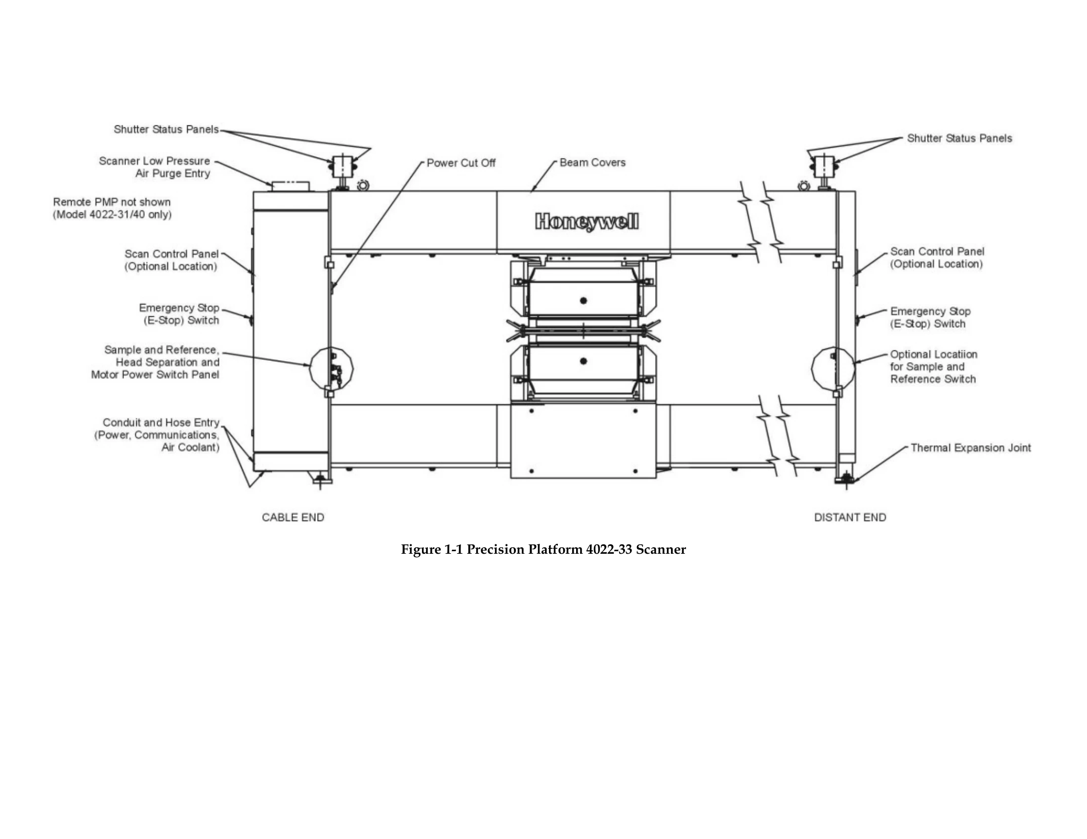
Consists of two rigid horizontal beams with precision-aligned tracks, rigid end supports housing electronics and drive system, power tracks for cables and hoses, and beam covers. The air purge system protects from process and mill conditions. It isolates from differential expansion and contraction, and carriages scan across the sheet.
Each beam includes a structural steel I-beam, fiberglass head carriage track, power track for cables and hoses, beam covers with optional seals, and head movement monitoring/control switches.
Uses clean, low-pressure air to purge contaminants, circulate air within the enclosure, and cool the head drive motor. Air purge is required in ambient temperatures above 55°C (130°F) or very dusty locations. With air purge, the scanner can operate up to 94°C (200°F).
Includes upper and lower head carriages, support arms, wheels, fiberglass head carriage tracks, a drive motor, reduction pulleys, pneumatic solenoid head separation clutch, and head drive belts. Belt tension is adjustable.
Switches monitor and control head movement. These include Preset (fixed reference), Limit (exceeding movement limit), Crash (stops scanning, alerts computer), and Emergency Stop (disables motor controller and sensors).
Supports house drive motor, electronics, and switches. Controls include Scan Control Panel (local control), Shutter Status Satellite Box, and Emergency Stop switch.
Buttons control scanning functions and enable sensors. LEDs indicate active functions. May include a key-operated switch for X-ray source functions.
| Switch | Function |
|---|---|
| Present | Provides a permanent fixed reference to the motor controller software to update the head position. Identifies approximate mid-beam position of head movement. |
| Limit | Alerts you if a head exceeds the horizontal-movement limit. The heads should not come within pproximately 14.0 in (355.6 mm) of the cable or motor end supports |
| Crash | Stops all scanning and alerts the computer that a head has passed a limit switch and come within aproximately 12 in (304.8 mm) of the end supports |
| Emergency stop (E-Stop) | Disables the scanning motor controller and disables sensor activation (where applicable) when pushed by an operator. |