Parts/Service for HV-D30

Parts/Service for HV-D30

Brand: HITACHI

Category: Industrial Marking

Document Type: Parts/Service

Language: EN

Uploaded: Nov. 21, 2025, 9:20 p.m.

Warranty Information

None

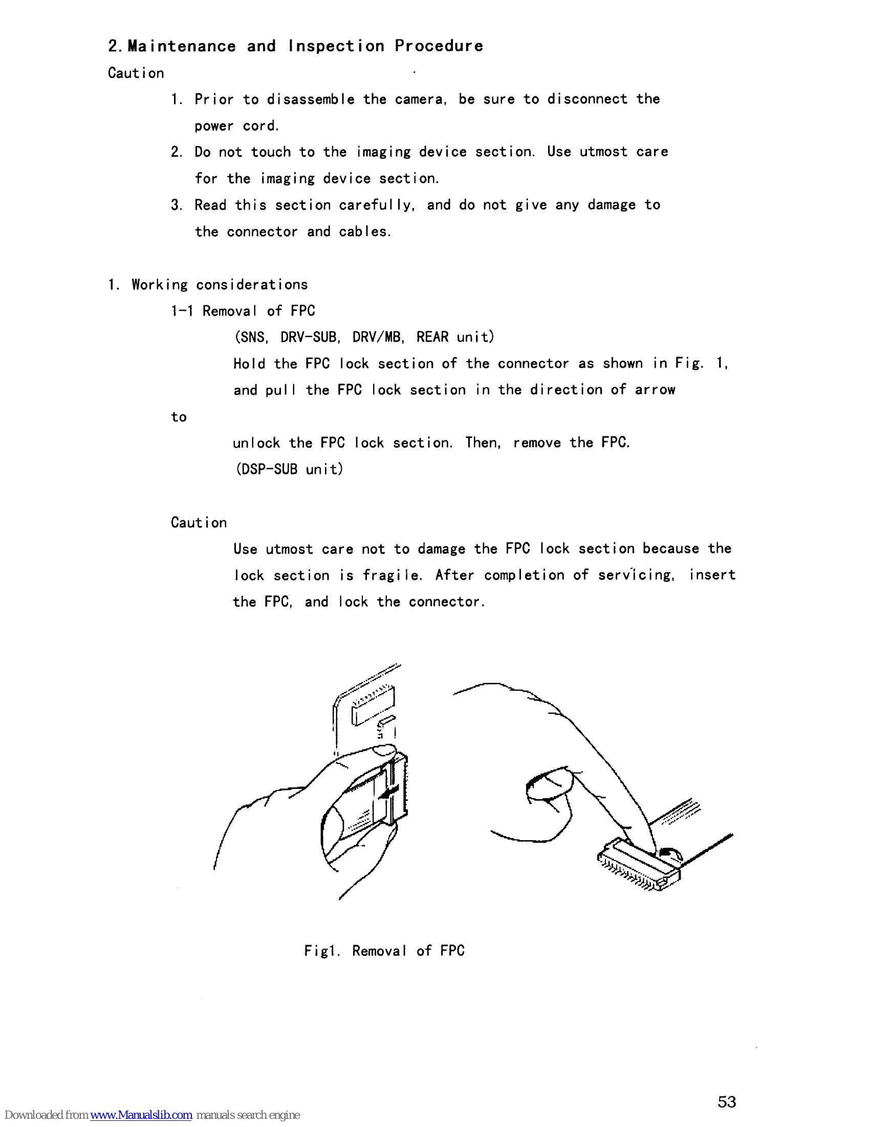
Maintenance and Inspection Procedure:

  • Prior to disassembling, disconnect the power cord.
  • Exercise extreme caution when handling the imaging device section.
  • Carefully read all instructions to avoid damaging connectors and cables.

Working Considerations:

  • FPC Removal: Hold the FPC lock section, pull in the direction of the arrow to unlock, then remove the FPC. Use utmost care as the lock section is fragile.

Disassembly Steps:

  • Top Cover & Chassis: Remove 8 screws to remove the top cover. Remove the top chassis to access PC boards.
  • PC Boards: Remove CPU, VDA/GL, or PWR boards from the DRV/MB board.
  • Front Block: Remove screws fixing ASP/DSP board and DRV/MB board. Remove screws fixing the front chassis. Disconnect tape cables as needed, but do not disconnect cables to SNS boards when removing the DRV-SUB board. Remove the front block with DRV-SUB and ASP/DSP boards.
  • Rear Block: Remove PWR board from DRV/MB. Remove screws for ASP/DSP board and DRV/MB board. Remove screws fixing the front chassis. Remove the rear block and disconnect tape cable between MB and REAR board.

Fuse Replacement:

  • Remove top cover and PWR board. Unsolder fuse F301 leads and remove the fuse. Insert a new fuse and solder leads.

Extension Boards:

  • Extension boards are available for CPU, VDA, and PWR boards.
  • Ensure correct connection to avoid damage.
  • Specific steps for connecting extension boards for ASP/DSP boards are provided.

Adjustments:

  • Standard Pickup Conditions: Specifies illumination, color temperature, lens, iris, power supply, ambient conditions, monitor settings, and test charts.
  • Power Supply Voltage: Instructions to check voltage at various points on the PWR unit.
  • Adjust Screen Settings: Details on how to access and use the adjustment menus (SC/GL, BAR&D/A, BLACK, CAM MODE, ADJUST MODES). Specific parameters like SC ADJ, H GL ADJ, RGB G LEV, BLACK LEVEL, GAMMA BAL1, MOD SHADING, FLARE are mentioned.

Troubleshooting and error codes

Item Adjustment Test point Initial setting Description Remarks
(1) Sub-carrier frequency ASP/DSP IC114 6pin Press the button to shift the cursor to 1.SC ADJ Press the or buttons for adjustment of sub-carrier frequency. NTSC: 3579545�b1;10Hz PAL : 4433619�b1;10Hz
(2) H GL ADJ MB TP41 Press the button to shift the cursor to 2. H GL ADJ. Press the or buttons for adjustment of voltage. Set the SW401 on the VDA board to IN side. 3.0�b1;0.2V Input BBS signal into DB15 connector, 14pin.(GL IN)
Privacy Policy