Brand: Haier
Category: Televisions
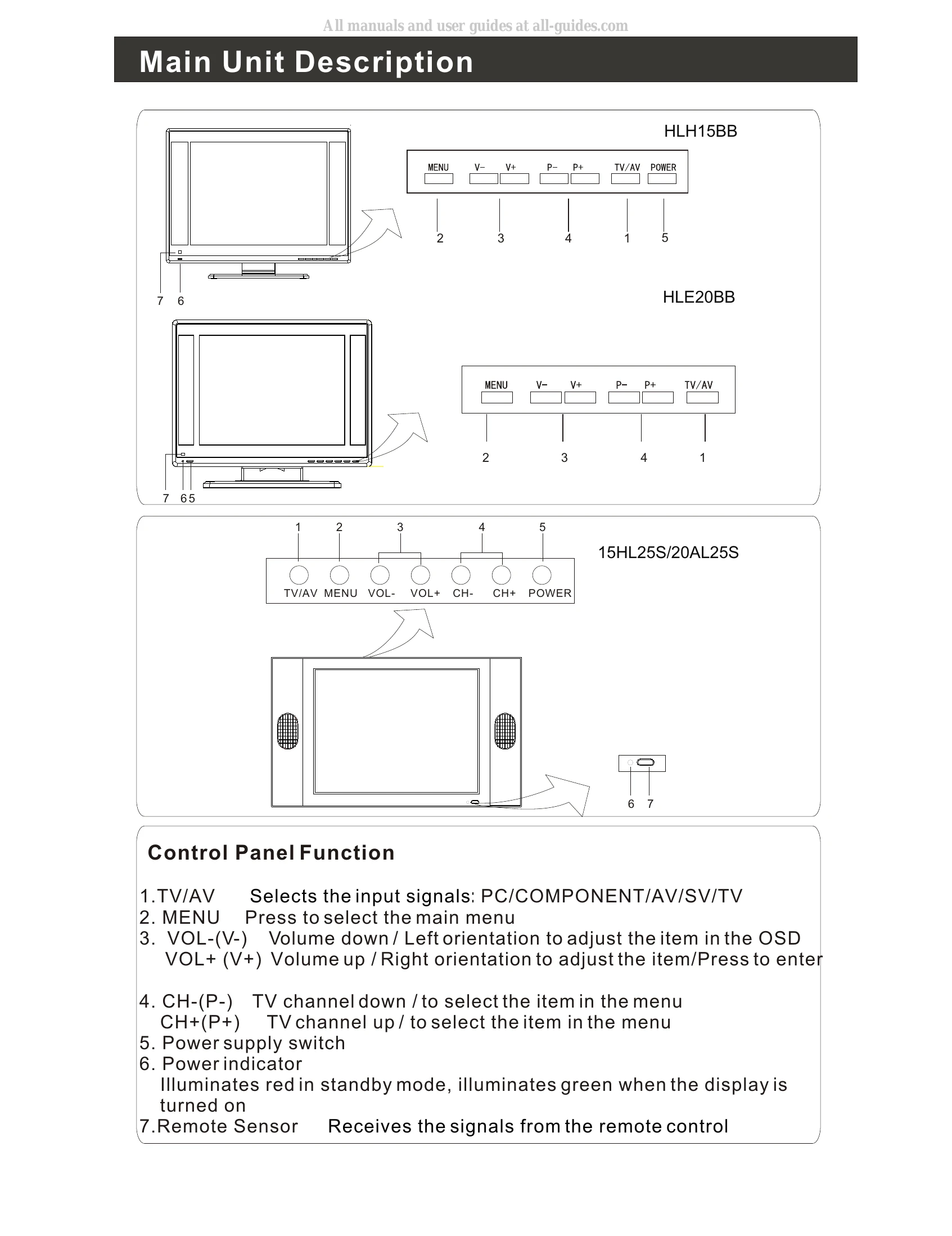
Document Type: Manual
Language: EN
Brand: Haier
Category: Televisions
Document Type: Manual
Language: EN
Uploaded: Nov. 21, 2025, 7:25 p.m.
DC Power Cord Socket: This TV operates on DC power. The voltage is indicated on the specifications page. Never attempt to operate the TV on ac power.
DVD/DTV Input: Connect a component device to these jacks
D-SUB Input: Connect to the VGA 15PIN analog output connector of the PC display card for PC display purpose
AV/S-VIDEO/COMPONENT Audio Input: Connect audio output from an external device to these jacks
PC Audio Input: Connect the PC output connector from a PC to the audio input port
Video Input: Connect video output from an external device to this jack
Antenna Input: Connect cable or antenna signals to the TV, either directly or through your cable box.
S-Video Input: Connect S-Video out from an S-Video device to the jacks.
Earphone port: Earphone port
| Problem | Possible Cause | Solution |
|---|---|---|
| Power Supply Trouble | F1 for 12V not correct | Check F1 and CN13 |
| F1 shorted | Check F1 for shortcut | |
| 5V not correct | Check E33(470 μ F/25V)for 5v | |
| Unit does not turn on | Turn on the set | |
| 350Khz switch signal incorrect | Check Pin3 U13 | |
| LDO or load shorted | Change LDO Or The load is in shorted | |
| Component failure (e.g., U13/MP1410ES & D17/IN5822) | Check U13/MP1410ES & D17/IN5822 | |
| Inductor L9 value incorrect | Check L9/47 μ H | |
| Voltage too high or low | Higt Voltage / Low voltage | |
| Component failure (e.g., U13/MP1410ES PIN5 & U13) | Check U13/MP1410ES PIN5 & U13 | |
| Capacitor C111 value incorrect | Check C111/0.01F | |
| Display Trouble | Black Screen | |
| 5V for BLON on CN7 incorrect | Check 5V for BLON on CN7 | |
| Unit does not turn on | Turn on or not | |
| 12V inverter input not correct | 12V inverter input ? | |
| Power supply incorrect | Check the power supply | |
| Inverter or self-proofed issue | Check the inverter or self-proofed | |
| SM5964 PIN43 incorrect | Check U25/SM5964 PIN43 | |
| MCU/Power Supply/Crystal issues | Check Mcu 1, power supply 2, Reset 3, Crystal | |
| CRT issue | Check the cirture for Q4/MMBT3904 | |
| White Screen | ||
| Panel power supply incorrect | Check power supply (for panel) | |
| Voltage Q23 incorrect | Check Q23 0~3.3V (5V or 12V), according to the volitage ) | |
| Signal output of U5/RTD2023B incorrect | Check signal output of U5/RTD2023B | |
| Voltage Q24 incorrect | Check voltage of Q24 | |
| U5/Power Supply/Time Circuit issues | Check U5 1,Power supply 2, Time circuit | |
| LCD or Panel Connector issue | Check LCD or Panel Connector | |
| Voltage between U25/SM5964 Q24 PIN3 incorrect | Check voltage between U25/SM5964 Q24 PIN3 or check U25 | |
| Power supply shorting | Turn to power suppy trouble shorting | |
| Voltage Q23 incorrect | Check voltage of Q23 | |
| Shorting in Q23 | Check Q23 (be care for the shorting ) | |
| Circuit between CN8 and CN9 incorrect | Check circuit between CN8 and CN9 | |
| Exceptional screen | ||
| Panel voltage incorrect | Select the right panel voltage | |
| Panel connector incorrect | Check the panel connector | |
| LCD issue | Check LCD | |
| Output net or connector issue | Check the output net, the connector | |
| U5/Power supply/Timer circuit issue | Check U5 For Power supply & timer circuit | |
| Audio Trouble | No Audio | |
| No audio signal input | Check audio signal input | |
| Volume/Mute incorrect | Check the set of volume, mute | |
| Signal from C11 incorrect | Check signal from C11 | |
| U20/TPA1517NE PIN7 incorrect | U20/TPA1517NE PIN7 | |
| Power U20 PIN8 incorrect | Check power U20 PIN8≥9.2V? | |
| Signal input U20 PIN1 and PIN9 incorrect | Check U20 PIN1 and PIN9 for signal input | |
| Signal output U20 PIN4 and PIN6 incorrect | Check U20 PIN4 and PIN6 for signal output | |
| Signal output U21 PIN60,61 incorrect | Chekc U21PIN60,61for signal output | |
| Audio input incorrect (AV:U21 PIN49,50, PC:U21PIN53,54) | Check input audio input AV:U21 PIN49,50 PC:U21PIN53,54 | |
| Peripheral audio devices issue | Check the peripheral audio devices | |
| Speaker issue | Check the speaker | |
| U25/SM5964 I/O interface (PIN6,12) incorrect | Check U25/SM5964 And U25 I/0 interface (PIN6,12) | |
| Component failure (e.g., U20 or E45/100) | Examine and repair U20 or E45/100 | |
| Net between U20 and U21 incorrect | Check the net between U20 and U21 | |
| Net between U20 and CN11 incorrect | Check between U20and CN11 | |
| Power output incorrect | Check net output for U20 | |
| Audio input U20 PIN1,9 incorrect | Check audio input PIN1,9 | |
| TV No Audio | ||
| TV has no audio, but has picture | TV no audio, having picture | |
| Audio and PC AV signal incorrect | Check audio and PC AV | |
| SAW2/M9370M30 PIN1 signal output incorrect | Check signal ouput of SAW2/M9370M30 PIN1 | |
| Component failure (e.g., U21) or power supply issue | 1, check SAW2 2. check U21 PIN29,30 3. check power supply of U21 4. make sure U21 is damaged | |
| Net between SAW2 Pin1 and C133 incorrect | Check the net between SAW2 Pinland C133/0.01μF | |
| Capacitor C133 value incorrect | Check C133 | |
| TV Audio abnormal | ||
| Noise and NICAM cannot be detected | Noise and NICAM can't be detected | |
| Audio system issue | Check the audio system | |
| Picture is not normal | Picture is normal? | |
| Audio setting incorrect | Select the right audio | |
| Component failure (e.g., C113, D26, R140) or SAW2 issue | Check C113/0.01UF、D26、 R140/0Ω or change SAW2 | |
| Requires re-searching | Search again | |
| Function Trouble | TV | |
| TV cannot search/No picture | TV can not search/No picture | |
| RF signal input incorrect | Check RF signal input | |
| Voltage T1/TDQ-6H3 PIN6 incorrect (should be 5V) | Check voltage T1/TDQ-6H3PIN6 for 5V | |
| Voltage T1 PIN3 incorrect (should be 0V) | Check voltage T1 PIN3 for 0V | |
| Voltage T1 PIN9 incorrect (should be 33V) | Check voltage T1 PIN9 for 33V | |
| I²C signal T1 PIN4,5 incorrect | Check I²C signal T1 PIN4,5 | |
| Signal T1 PIN11 incorrect | Check signal T1 PIN11 | |
| Voltage T1 PIN1 incorrect (should be >1V) | Check voltage T1 PIN1 >1V | |
| RF device issue | Examine and repair RF device | |
| Net between T1 PIN11 and U21 PIN24,25 incorrect | Check the net between T1 PIN11 and U21 PIN24,25 ;Power supply for U21 | |
| Component T1/TDQ-6H3 issue | Change T1/TDQ-6H3 | |
| Circuit issue | Examine and repair The circuit | |
| I²C net issue (connect with U25/SM5964 PIN16,17) | Check I²C net (connect with U25/SM5964 PIN16,17 | |
| Circuit issue | Examine and repair circuit | |
| Component R267/0Ω issue | Examine and repair R267/0Ω | |
| Power supply net issue | Examine and repair The power supply net | |
| PC | ||
| Picture not in center | Picture not in center | |
| Auto adjust incorrect | Auto adjust | |
| Missing color | Missing color | |
| RGB input incorrect | Check U5 RGB input | |
| Reset incorrect | Reset | |
| R,G,B circuit issue | Check R,G,B circuit | |
| Picture dithering | Picture dithering | |
| VS,HS signal incorrect | Check VS,HS signal | |
| OSD setting incorrect | Check OSD setting | |
| Reset incorrect | Reset | |
| VS.HS issue | Check VS.HS | |
| No signal | No signal | |
| VS.HS issue | Check VS.HS | |
| AV/SV SCART | ||
| No signal | No signal | |
| VS, HS circuit issue | Check VS, HS circuit | |
| Reset incorrect | Reset | |
| Missing color | Missing color | |
| RGB signal input for U5 incorrect | Check RGB signal input for U5 | |
| RGB issue | Check RGB | |
| Power supply of U21 incorrect | Check the circuit for power supply of U21 | |
| No signal except PC | No signal except PC |