Manual for 113.299310

Manual for 113.299310

Brand: CRAFTSMAN

Category: Other

Document Type: Manual

Language: EN

Uploaded: Sept. 12, 2025, 4:29 a.m.

Manual Publish Date: 1999-03-01

Warranty Information

None

RULES FOR SAFE OPERATION

  • READ ALL INSTRUCTIONS
  • KNOW YOUR POWER TOOL
  • KEEP THE WORK AREA CLEAN
  • ALWAYS WEAR SAFETY GLASSES
  • ALWAYS DISCONNECT SAW FROM POWER SUPPLY BEFORE MAKING ADJUSTMENTS OR ADDING ACCESSORIES
  • SAVE THESE INSTRUCTIONS

Look for this symbol to point out important safety precautions. It means attention!!! Your safety is involved.

LOOSE PARTS LIST

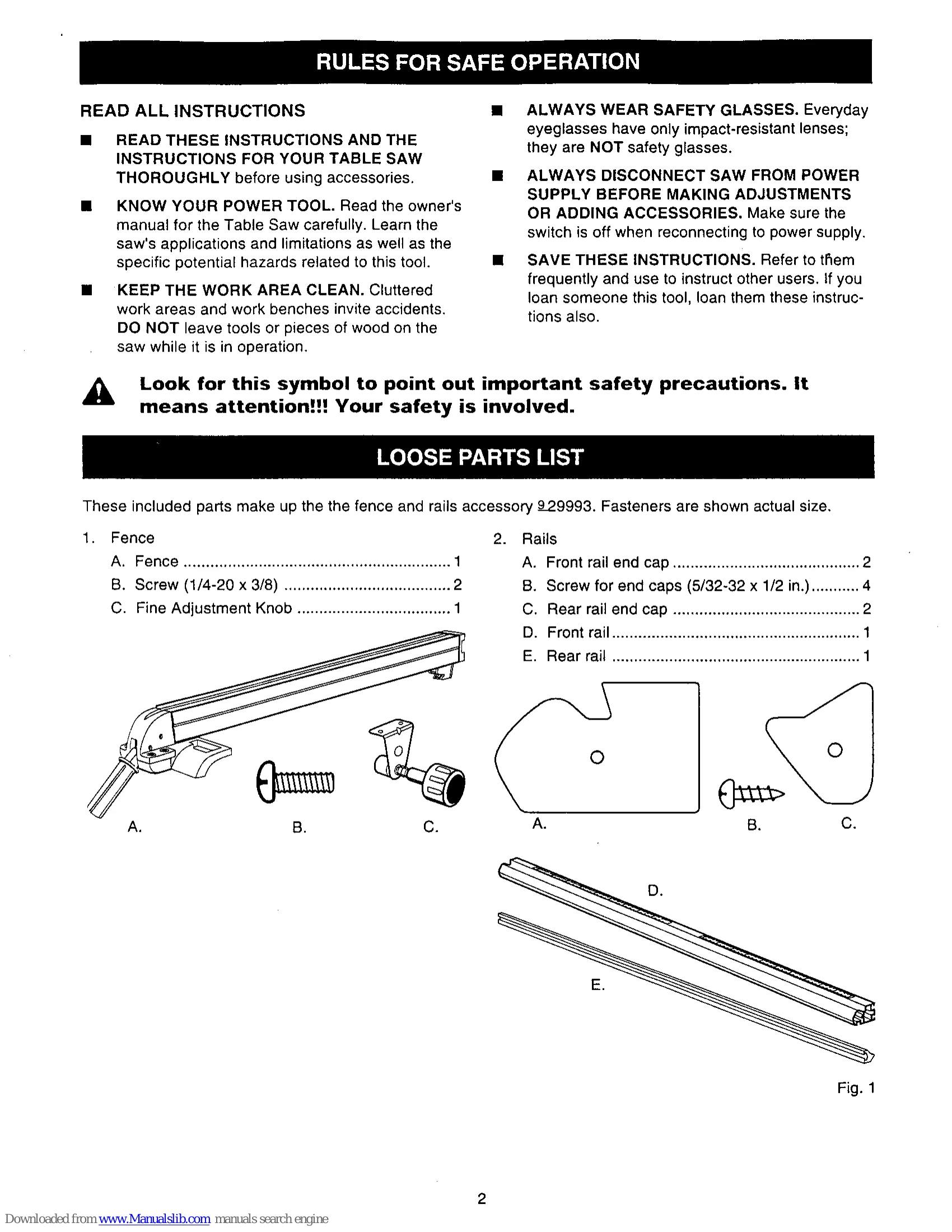
These included parts make up the the fence and rails accessory 929993. Fasteners are shown actual size.

1. Fence

  • A. Fence
  • B. Screw (1/4-20 x 3/8)
  • C. Fine Adjustment Knob

2. Rails

  • A. Front rail end cap
  • B. Screw for end caps (5/32-32 x 1/2 in.)
  • C. Rear rail end cap
  • D. Front rail
  • E. Rear rail

PREPARATION

REMOVING THE SWITCH AND RAILS

  • Remove the front rail end caps.
  • Under the front rail, loosen the switch screws and slide the switch off of the rail.
  • Remove the rear rail end caps.
  • Under the table, loosen all of the hex nuts on the square head bolts that hold both front and rear rails.
  • Carefully slide the rails off of the bolts and the table.

INSTALLATION

INSTALLING THE REAR RAIL

WARNING: Front and rear rails must be carefully aligned to reduce the risk of kickback, which can cause serious injury.

  • From the carton, remove the rear rail and the following hardware: Right and left end caps for rear rail, 2 screws (5/32-32 x 1/2 in.) for end caps.
  • Position rail so that the right hand edge extends 2-1/2 in. beyond the table extension.
  • Push the rail against table and tighten each hex nut with a 12 mm wrench.
  • Put the end caps on the rail ends. Insert the screws and tighten with a phillips screwdriver.

INSTALLING THE FRONT RAIL

  • Locate the front rail and the following hardware: Right and left end caps for front rail, 2 screws (5/32-32 x 1/2 in.) for end caps.
  • The back of the rail has two slots. Carefully slide the upper slot over the bolts.
  • Align the rail left to right - Match the 7-1/8 in. mark on the right scale to the right edge of the saw base (main table).
  • Snug the rail against table. Finger-tighten each nut on the table and extensions.

INSTALLATION (Continued)

  • Insert the two remaining pan head screws into holes in the fine adjustment knob bracket.
  • Attach the fine adjustment knob bracket to the bottom of the fence head on the right or the left side of the fence handle. Securely tighten the two screws.

MOUNTING THE SWITCH

  • Locate the switch assembly. The fasteners should still be attached.
  • Holding the switch to the front, insert and slide the two square nuts into the lower slot of the front rail.
  • WARNING: Place the switch out of the immediate work area to avoid accidentally turning it off during operation.
  • Slide the switch assembly to a convenient position, leaving ample clearance for the handwheel. Tighten securely with a screwdriver.
  • Attach the front rail end caps and screws with a phillips screw driver.

ALIGNMENT

ALIGNING THE RIP FENCE AND FRONT RAIL

  • The rip fence scale indicator is installed on the right side of the rip fence but can be removed and reinstalled on the left side if needed.
  • Hook the back of the rip fence over the rear rail. Lower the front of the rip fence into the groove on the front rail.
  • Slide the rip fence back and forth. It should move freely with about 1/16 in. clearance below the rip fence.
  • Remove the rip fence and repeat on the other side of the blade. When the fence rides smoothly, tighten all rail hex nuts with a 12 mm wrench.
  • Push in the micro-adjust knob and turn it. The gear on the shaft assembly will engage the rack teeth on the rack and will move the fence assembly left or right.
  • Push down on the rip fence handle to lock the rip fence in place.

CHECKING RIP FENCE AND BLADE ALIGNMENT

  • The rip fence is self-aligning but should be checked before first use.
  • WARNING: Failure to align the rip fence to the blade can cause jams and kickback, resulting in serious personal injury.
  • Slide the rip fence to the miter gauge groove, which is parallel to blade. Do not lock the rip fence.
  • Place a framing square against the blade, with the long end under the rip fence at the front. Note the distance.
  • Move the square to the back and measure the length from other end of the fence.
  • If the distances are different, loosen the four screws around the rip fence handle with a 6 mm hex key. Alternate the order (remove the screw opposite, not next to the first one).
  • Hold the fence handle against the front rail and align the rip fence with the blade.
  • Retighten the screws in alternating order and check the alignment.
  • Repeat until the rip fence is aligned.
Privacy Policy