Server CPU Module Bay Layout
The Cisco UCS C480 M5 server features two CPU module bays: a lower bay (Bay 1) and an upper bay (Bay 2). CPUs are numbered sequentially from CPU 1 to CPU 4. Each CPU has six memory channels, and each channel supports up to two memory DIMMs, for a total of up to 24 DIMMs per CPU and 48 DIMMs per server.
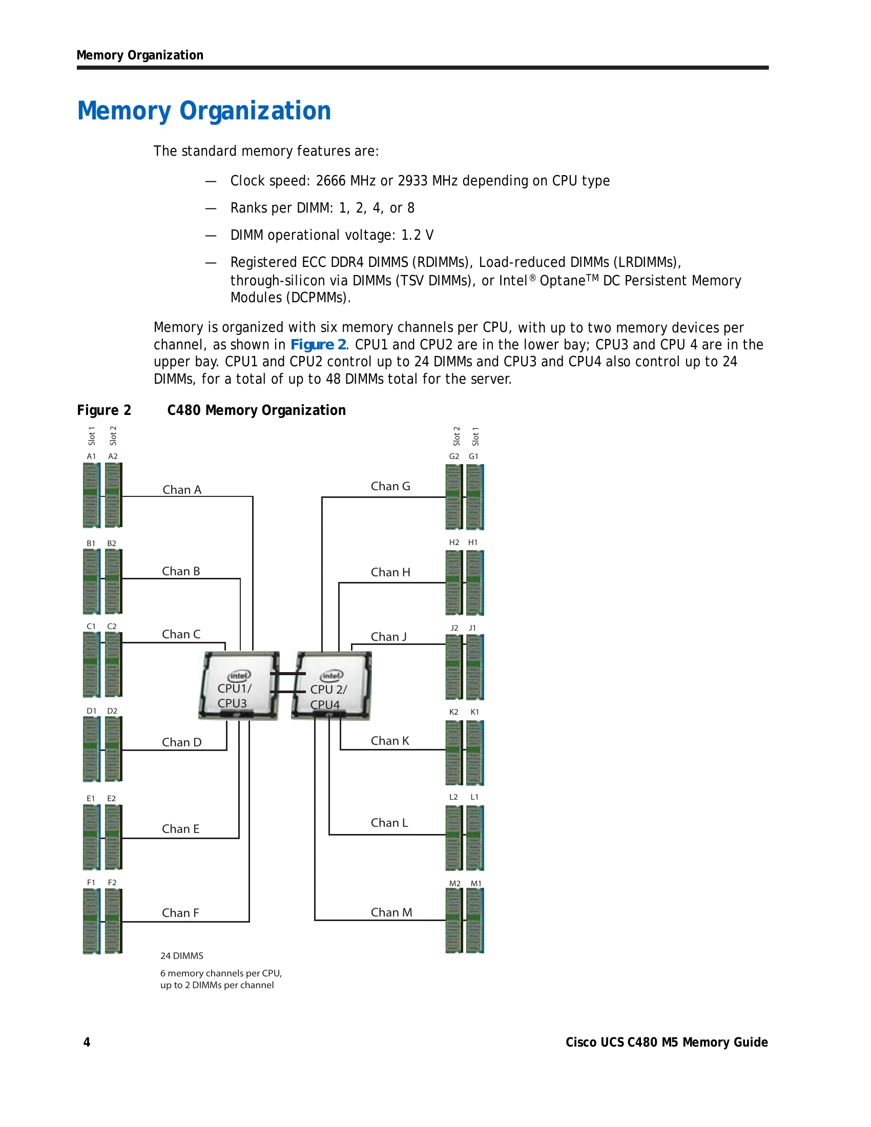
Memory Organization
Memory is organized with six channels per CPU. Standard memory features include clock speeds of 2666 MHz or 2933 MHz, 1, 2, 4, or 8 ranks per DIMM, and a DIMM operational voltage of 1.2 V. Supported memory devices include RDIMMs, LRDIMMs, TSV DIMMs, and Intel® Optane™ DC Persistent Memory Modules (DCPMMs).
Memory Configurations and Modes
The server supports three RAS modes: Independent Channel, Mirrored Channel, and Lockstep Channel. Memory mirroring is supported on DIMMs but not DCPMMs, reducing available memory by 50%. Mixing of Non-Mirrored and Mirrored modes is not allowed. DIMM types (RDIMMs, LRDIMMs, TSV-RDIMMs) and ranks should not be mixed within a channel for optimal performance. DCPMMs require second-generation Intel Xeon Scalable processors and must be of the same size.
DIMM Population Rules
When populating DIMM slots, populate slot 1 (blue) first. For optimal performance, use identical DIMM types (speed, size, ranks) within the server. Populate at least one DIMM per memory channel per CPU. Multiples of 12 DIMMs are recommended for optimal configurations. Specific rules apply when mixing DIMM types, capacities, and ranks.
Recommended DIMM Configuration
The manual provides recommended memory configurations for 2nd Generation Intel Xeon Scalable Processors and Intel Xeon Scalable Processors, detailing specific DIMM placements in blue and black slots for various total system memory sizes and DIMM types (R, LR, TSV-R). It also outlines DIMM/DCPMM configurations for mixed memory environments, specifying DIMM and DCPMM quantities and their impact on total capacity.
Installing a DIMM or DIMM Blank
Installation involves opening DIMM connector latches, pressing the DIMM evenly into the slot until it clicks, ensuring the notch aligns, and then fully seating the latches. All slots must be populated with either a DIMM or a DIMM blank.